The Singer 431G has a “Cloth Plate and Accessories Container with Bed Extension” that can be removed to allow freearm sewing by pressing the button on the Locking Lever.
The Locking Lever assembly consists of several small parts that may require cleaning, servicing or replacement.
This mechanism is difficult to access because it is covered entirely by the large aluminum Feed Bar.
I was able to access the screws that hold the latch assembly loosening several parts to allow the Feed Bar to move away from the machine bed.
These are the steps that I took to expose the latch screws.
- Set the machine on its right (handwheel) side.
- Remove the Bed Cover Plate on the bottom.
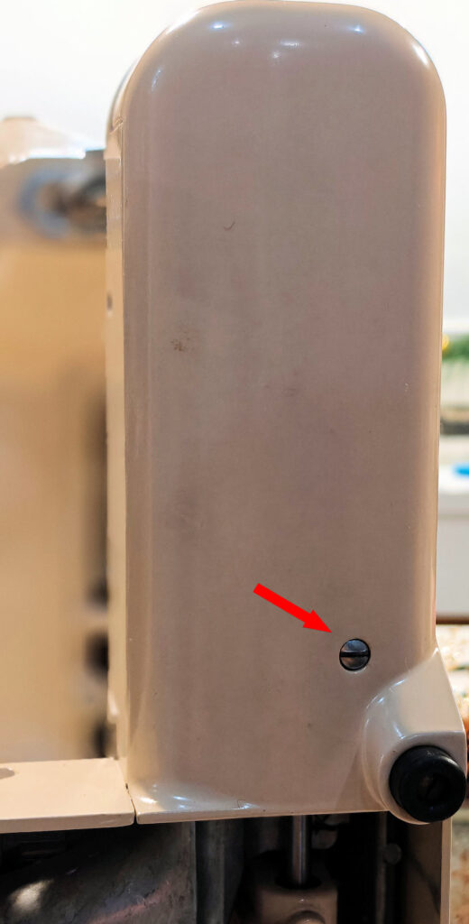
- Remove the Tubular Bed Cover screw and pull the cover toward the end to release it.
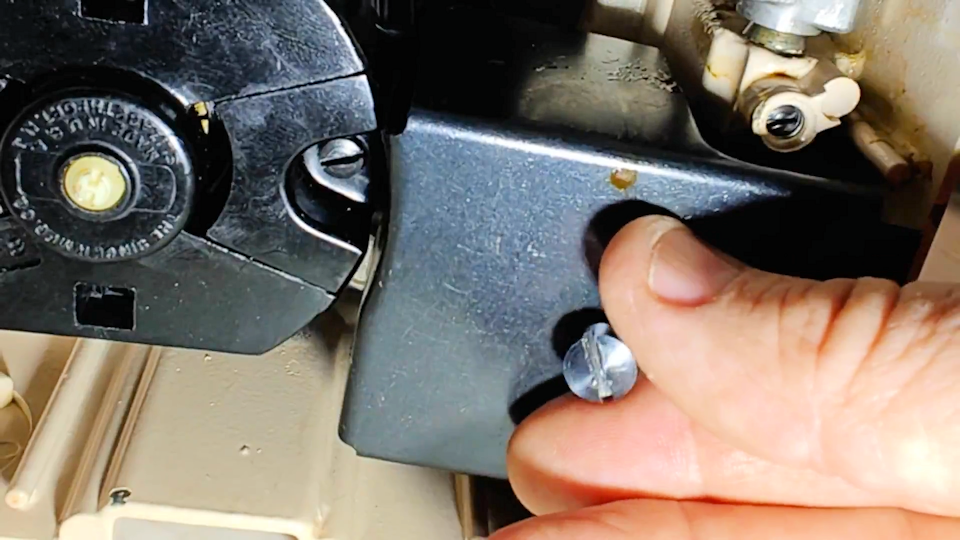
- Remove the Motor Hold Down Plate.
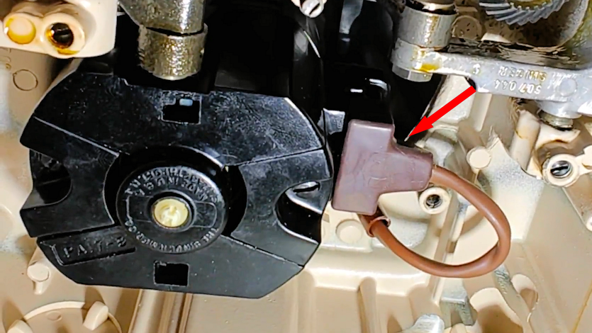
- Remove the Terminal Plug from the Motor.
- Pull the Motor down and out.
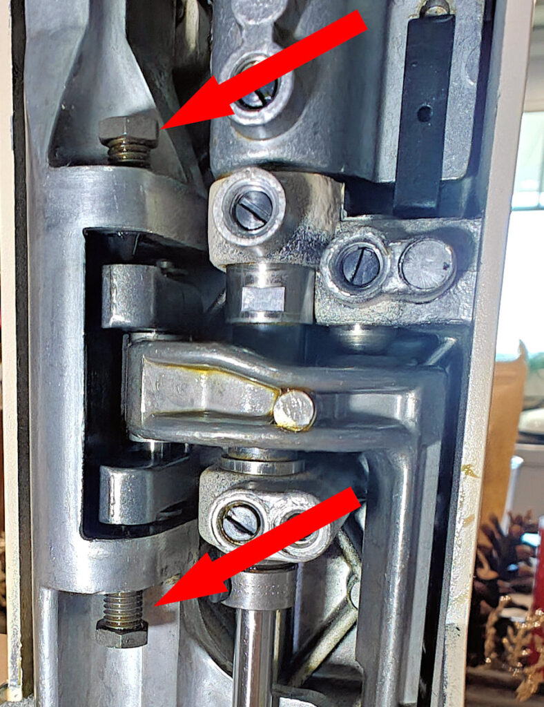
- Loosen the Feed Bar Connecting Block nuts with an 8mm socket and unscrew the Feed Bar Connecting Block screws. Note: When you reinstall them, center the bar so the presser foot is centered in the slots in the needle plate.
- You do not need to remove the Feed Dogs.
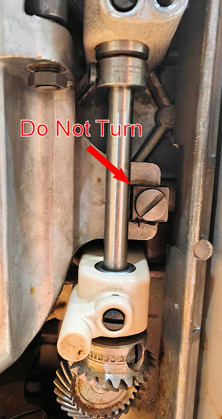
- Do not turn the Feed Bar Aligning Screw.
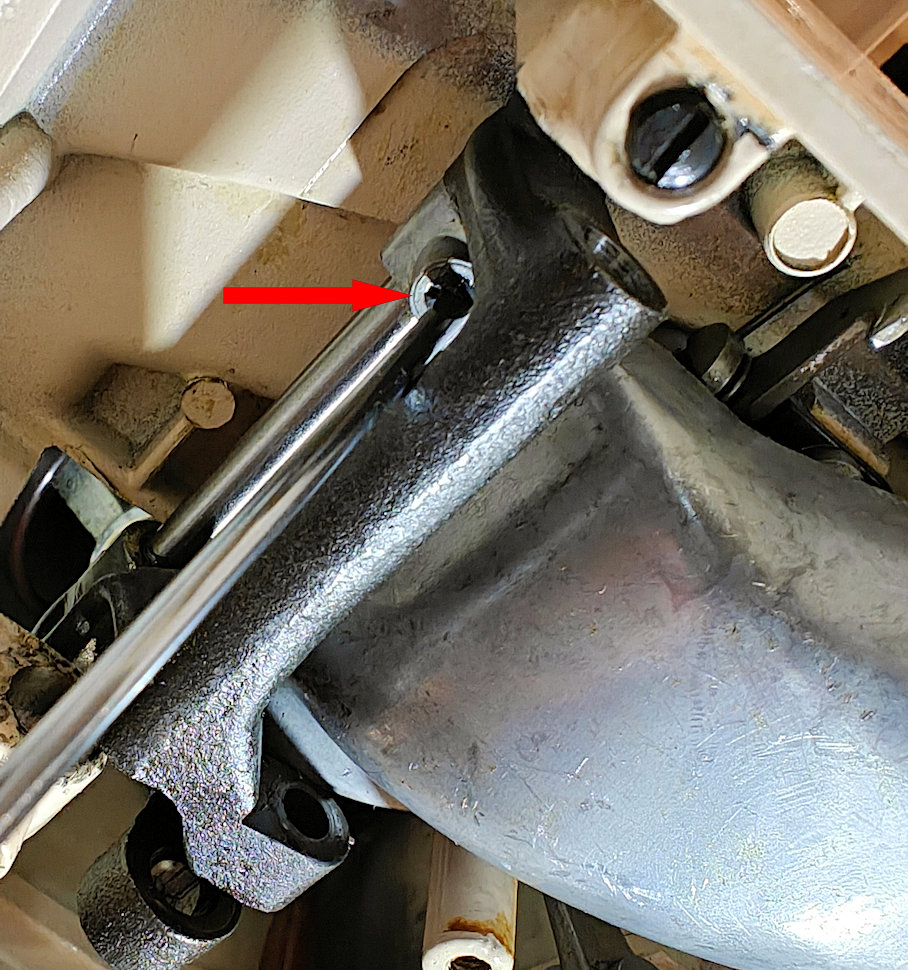
- Disconnect the Feed Fork from the Feed Rock Shaft by loosening the 8mm nut and pushing out the eccentric screw. Note: The eccentric screw adjusts the height of the feed dogs at their highest point. If it is adjusted too high when you reassemble the machine, you will feel a resistance or a binding when you rotate the handwheel through a full rotation. Adjust it so takes the feed dogs as high as possible without causing the machine to push and bind.

- Remove the set screws holding the Feed Rock Shaft Centers in place.
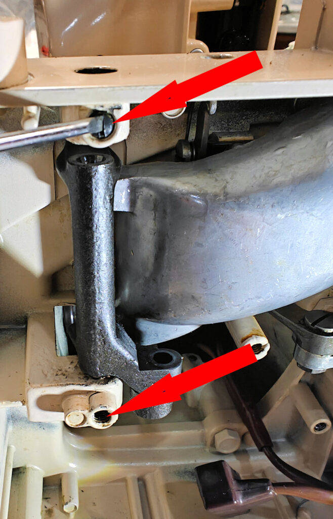
- Push the centers out to free the Feed Rock Shaft. You can use a small set of diagnonal cutters to help push the centers out. If they do not come out easily, use a heat gun to heat the aluminum around the centers. Once they are heated, they should be easy to push out.
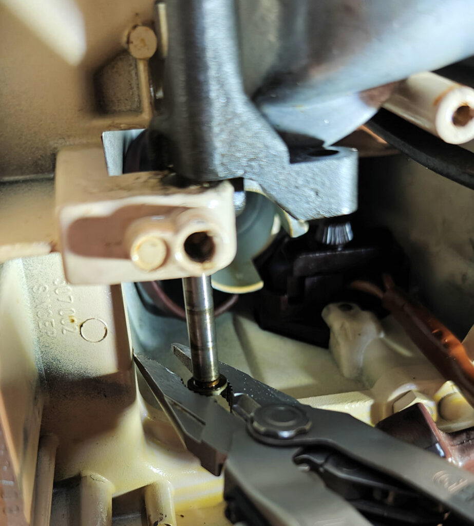
- Once you get the centers out, you should be able to rotate the Feed Rock Shaft to access the Feed Rock Shaft Hinge Pin Set Screw.
- After the set screw is removed, you can pull the shaft out to separate the aluminum Feed Bar from the steel Rock Shaft.
- Remove the steel Feed Bar and set it aside.
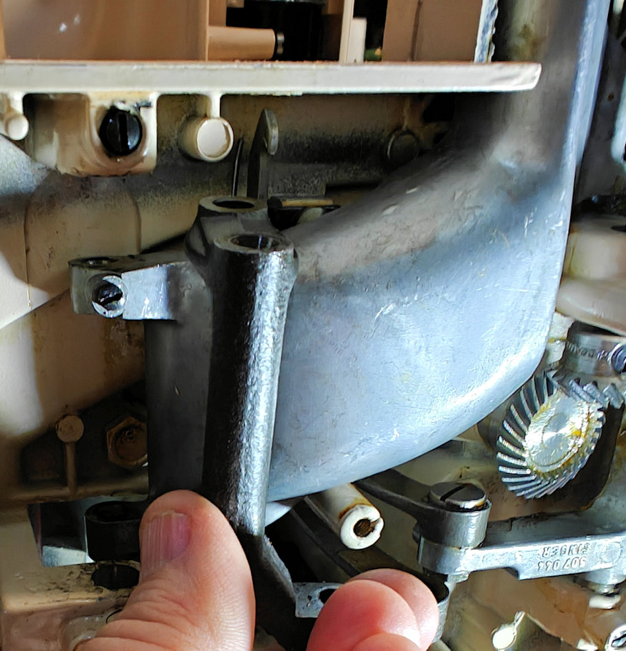
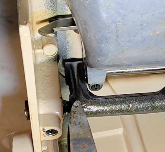
- This will allow the aluminum Feed bar to drop appoximately one inch so you can access the latch screws with a right-angle screwdriver.
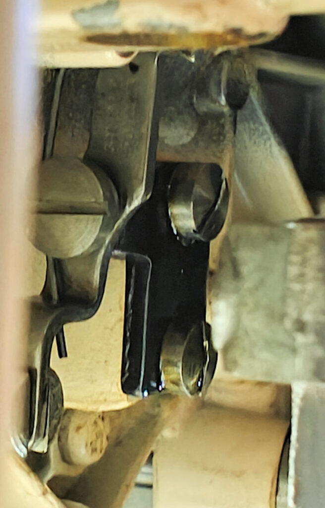
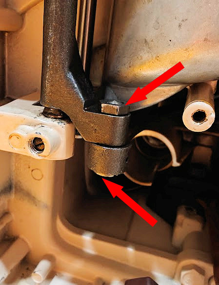
- This is the view of the latch screws after the bar is dropped.
- Reassemble in reverse order.
- The only adjustment you should need to make is the adjustment of the eccentric screw. Notes are in the teardown section for this portion.
- Assuming the specifications for the 431G and the 401A are the same, adjust this eccentric so the feed dogs protrude above the needle plate by 0.040 – 0.043 inches at their highest point. This is approximately the thickness of a standard paper clip.